
Home / Articles / Reinforced Concrete BA-03
Columns and Slenderness in TS 500: As the Column Bends, the Moment Grows
In a long, slender column the axial load magnifies the bending by itself. TS 500 Clauses 7.4 and 7.6: dimension and reinforcement rules, limits for neglecting slenderness, and moment magnification — plus the slenderness check we added because the site’s engine lacked it.
1. Second order: as the column bends, the moment grows
When a column carrying axial load bends, the load acts with an eccentricity relative to the column axis and produces an additional moment of its own. This second-order moment increases the bending, and the increased bending enlarges it further. In a short column the effect is small; in a long, slender column it can govern. TS 500 calls this the slenderness effect and gives two routes in Clause 7.6: a general method based on second-order analysis and a moment magnification method.
2. Dimensions and reinforcement first
TS 500 Clause 7.4.1 sets the basic conditions for columns: width at least 250 mm for rectangular sections (diameter at least 300 mm for circular ones); Nd ≤ 0.9·fcd·Ac (Eq. 7.7); longitudinal reinforcement ratio at least 1% (down to 0.5% if at least 1.3 times the required steel is provided) and at most 4% (6% in lap zones); longitudinal bars at least Φ14; tie diameter not less than one third of the largest longitudinal bar, spacing not more than 12 times the smallest longitudinal bar and 200 mm.
3. When is a column slender?
The measure is the slenderness ratio: effective length over radius of gyration, ℓk/i. For rectangular sections i may be taken as 30% of the dimension in the bending direction. The effective length is the clear length times a factor k reflecting the end restraint (ratio α of column to beam stiffnesses) and whether storey sway is prevented (Eqs. 7.14–7.16).
Slenderness may be neglected if: in a braced storey ℓk/i ≤ 34 − 12·(M1/M2) ≤ 40 (Eq. 7.17); in an unbraced storey ℓk/i ≤ 22 (Eq. 7.18). When the end moments bend the column in single curvature (M1/M2 = +1) the limit drops to 22; in double curvature it rises to 40. Beyond a slenderness ratio of 100 the approximate method may not be used; a second-order analysis is required (7.6.1).
4. Moment magnification
In the approximate method the larger end moment is magnified by a factor. For a braced column:
β = Cm / (1 − 1.3·Nd/Nk) ≥ 1 (7.24), Cm = 0.6 + 0.4·(M1/M2) ≥ 0.4 (7.25), Nk = π²(EI)/ℓk² (7.19), (EI) = 0.4·Ec·Ic/(1 + Rm) (7.21)
Rm is the sustained-load share of the axial force: creep under sustained load reduces stiffness. The design moment is Md = β·M2, and M2 may not be less than the moment from the minimum eccentricity (emin = 15 + 0.03h mm, Eq. 6.16). In unbraced storeys a storey factor βs is also computed, ΣNd ≤ 0.45·ΣNk must hold, and for very slender columns the two factors are multiplied (Eqs. 7.27–7.29).
An example (the site’s new function, verified by hand): 400×400 mm, C30, clear length 4 m, braced, k = 1, Nd = 1500 kN, Rm = 0.6, M1 = 60, M2 = 100 kNm (single curvature). ℓk/i = 33.3 > 34 − 12·0.6 = 26.8: the column is slender. Ec = 31,801 MPa, Nk = 10,462 kN, Cm = 0.84, β = 1.032, Md = 103.2 kNm.
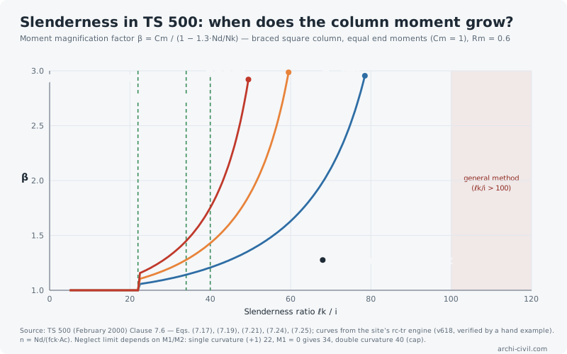
The figure shows how sensitive β is to the axial load level: for a column with n = Nd/(fck·Ac) = 0.35, β = 1.43 at ℓk/i = 40 and 3.09 at 60. As load grows, the column approaches instability at a much shorter length.
5. What we found in the site’s engine
- There was no slenderness check. The site’s column presizing tool said "slenderness is checked separately", but no function did so. A new function implementing all of TS 500 Clause 7.6.2 was added (the example and figure above come from it).
- Detailing rules are not checked: Φ14, tie diameter and spacing, 300 mm between restrained bars. These are outside the engine’s scope; the designer must check them separately.
- Two relaxations are not used: ρ ≥ 0.5% (with the 1.3 condition) and ρ ≤ 6% at laps. The engine stays on the safe side.
- Pure axial capacity: TS 500 gives no explicit equation for it; the engine uses the gross section and counts the concrete displaced by steel twice (about 0.8% high at 1% steel). Since the Eq. 7.7 limit is far below this value in design, results are not affected.
- A notation in the source: in the upper bound of Eq. 7.14 TS 500 writes "0.85 + 0.05·α1"; in the ACI 318 counterpart this term uses the smaller of the two end values of α. The function applies the TS 500 text as printed.
6. Rules
- Compute the slenderness ratio first. In most columns it can be neglected — but the calculation shows that, not an assumption.
- Single curvature is the worst case. If the end moments bend in the same direction the neglect limit drops to 22.
- Sustained load reduces stiffness. As Rm grows, Nk falls and β rises.
- Take sway seriously. In an unbraced storey the limit is 22 and the storey as a whole must satisfy ΣNd ≤ 0.45·ΣNk.
References
- TSE. TS 500 Requirements for Design and Construction of Reinforced Concrete Structures (in Turkish), February 2000 — Clauses 6.3.10 (Eq. 6.16), 7.4.1 (Eqs. 7.7–7.10), 7.6.1, 7.6.2 (Eqs. 7.13–7.29); Eq. (3.2) (Ec). Official text.
- archi-civil.com engine/rc-tr.js — columnSlendernessTS500 (v618) and an audit of the column functions: tests/v618-ba03.test.js.
The numbers in this article were produced by the site's engines; code values are given with their clause numbers.