
Home / Articles / Protective Structures PRT-04
Blast-Resistant Reinforced Concrete: Rotation Limits and Dynamic Strength
Of two RC walls of the same thickness, one can fail under blast at 2° rotation and the other at 12°; the arrangement of the reinforcement makes the difference. Fast loading, meanwhile, strengthens the material. The two key ideas of UFC 3-340-02 Chapter 4, with the source table.
1. Earthquakes and explosions ask the same question
An earthquake shakes a building several times within seconds; an explosion strikes a wall once within milliseconds. In both the question is the same: where does the energy go? In earthquakes the answer is ductility and controlled damage (R and D factors). So it is in explosions, with two differences. First, a material loaded this fast is stronger. Second, how far a protective element can rotate is set almost entirely by its detailing. Chapter 4 of UFC 3-340-02 is built on these two ideas.
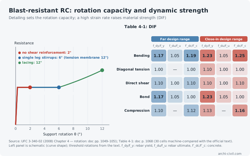
2. Detailing sets the rotation capacity
UFC 3-340-02 describes the behaviour of a reinforced concrete element under blast by its resistance–deflection curve and measures it by the support rotation θ at the element ends (doc pp. 1049–1051):
- 2°: the compression concrete crushes. For elements without shear reinforcement this is the limit; the element loses its integrity.
- 6°: attainable under flexural action with single leg stirrups (shear reinforcement). With sufficient lateral restraint the element can act as a tension membrane and rotate up to 12°.
- 12°: lacing restrains the reinforcement through its entire strain-hardening region; rotation continues until the reinforcement fails in tension.
So two walls of the same thickness and concrete can fail at 2° and at 12°; the only difference is the arrangement of the reinforcement. Lacing is hard to build; UFC therefore offers single leg stirrups as an easier option, but stirrups are less effective than lacing at very close charge separations.
3. Fast loading strengthens the material: DIF
Materials show higher strength as the loading rate increases. UFC accounts for this with the dynamic increase factor (DIF): dynamic strength = DIF × static strength (§4-13.2, doc p. 1060). The values of Table 4-1 (doc p. 1068):
| Type of stress | Far design range | Close-in design range | ||||
|---|---|---|---|---|---|---|
| fdy/fy | fdu/fu | f′dc/f′c | fdy/fy | fdu/fu | f′dc/f′c | |
| Bending | 1.17 | 1.05 | 1.19 | 1.23 | 1.05 | 1.25 |
| Diagonal tension | 1.00 | — | 1.00 | 1.10 | 1.00 | 1.00 |
| Direct shear | 1.10 | 1.00 | 1.10 | 1.10 | 1.00 | 1.10 |
| Bond | 1.17 | 1.05 | 1.00 | 1.23 | 1.05 | 1.00 |
| Compression | 1.10 | — | 1.12 | 1.13 | — | 1.16 |
Three patterns stand out. DIF is larger in the close-in design range, because loading is faster (1.17 versus 1.23 for rebar yield in bending). Ultimate strength increases much less than yield strength (1.05). For diagonal tension no increase is taken in the far range (1.00): a deliberate caution for a brittle failure mode.
Note: all 30 cells of Table 4-1 were machine-compared with the official text in the site's code pack (data/code-packs/US/ufc-3-340-02-ch4.json).
4. When the charge is very close
When the charge is very close to the element face, local punching and shear failure can govern. Per UFC, non-laced elements designed for close-in effects need Type A, B or C single leg stirrups; if the charge is at a scaled distance Z < 1.0 ft/lb1/3 (about 0.40 m/kg1/3), Type C stirrups or lacing must be used (doc p. 1094).
Chapter 4 gives no single numeric threshold for the "close-in" versus "far" design range; this is a designer's classification and decides which column of Table 4-1 to read.
5. Rules
- Choose the rotation target first, then the detailing. Beyond 2° requires shear reinforcement; beyond 6°, lateral restraint or lacing.
- Read DIF from the right column. Applying close-in values to the far range overstates strength.
- Give no increase to brittle failure modes. The 1.00 values in Table 4-1 are deliberate caution.
- Test the material model against its own material. In detailed numerical models, the consistency of constitutive parameters must be checked separately (see HES-05).
References
- U.S. DoD (2008). UFC 3-340-02: Structures to Resist the Effects of Accidental Explosions, 5 December 2008 — Chapter 4: doc pp. 1049–1051 (resistance–deflection, rotation limits), p. 1060 (§4-13.2 DIF), p. 1068 (Tablo 4-1), p. 1094 (stirrup types for close-in blasts).
- archi-civil.com code pack data/code-packs/US/ufc-3-340-02-ch4.json — Table 4-1 machine-compared with the official text (v605); tests/v605-ufc-ch4.test.js.
The numbers in this article were produced by the site's engines; code values are given with their clause numbers.