
Home / Articles / Protective Structures PRT-10
Suppressive Shields: Catching the Explosion at Its Source
Instead of making the building resist the blast, catch the blast at its source: a vented steel enclosure. UFC 3-340-02’s approved shield groups, two design parameters and a ratio that varies a hundredfold across the groups.
1. Catching the explosion at its source
So far the protective structures series has asked the same question: when a blast reaches a structure, how much can the structure take? A suppressive shield turns the question around: catch the explosion at its source. UFC 3-340-02 defines it as a vented steel enclosure that controls or confines the hazardous blast, fragment and flame effects of detonations (§6-23). It is used around hazardous operations such as munitions loading, assembly and packing; the design details are in a separate handbook (HNDM 1110-1-2, 1977).
A shield is an alternative to conventional protective barriers, total containment or large separation distances. According to UFC it is attractive especially when fragment hazards are severe and the explosive sources are concentrated (§6-25).
2. Approved groups and levels of protection
In 1977 the U.S. Department of Defense Explosives Safety Board approved five shield groups: Groups 3, 4, 5, 6 and 81 mm (§6-24.1). Table 6-4 summarises the groups by hazard and protection: groups designed for high blast and severe fragment hazards halve the blast pressure at intraline distance; others provide a Category I hazard level at a given distance from the shield (between 1 and 19 ft). The table’s note states the shield’s most basic function: all shield groups contain all fragments.
3. Two design parameters
The charge parameters that govern the choice of a shield come down to two numbers (§6-26.2, Table 6-5): the ratio of charge weight to the shield’s internal volume, W/V (loading density), and the scaled distance Z = R/W1/3 from the centre of the charge to the nearest wall or roof.
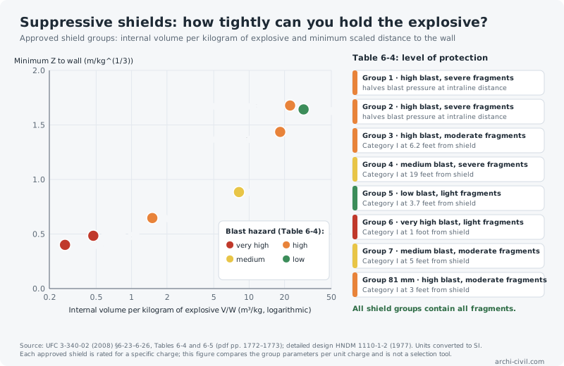
The figure shows a clear pattern: shields that hold the explosive more tightly (less volume per kilogram) hold it closer to the wall, and these are the groups designed for higher blast hazards in Table 6-4. Group 6A needs about 0.27 m³ of internal volume per kilogram with a minimum scaled distance to the wall of 0.40 m/kg1/3; Group 5 about 29 m³ and 1.64 m/kg1/3. So the volume needed per unit charge varies by about 100 times across the groups.
For a sense of scale, with a caveat: applied to a 10 kg charge, these ratios would require about 2.7 m³ of internal volume for Group 6A and about 290 m³ for Group 5. But every approved shield is rated for a specific charge; this calculation is not a selection, only a way to grasp the size of the parameters.
4. A shield is not a building but part of a process
UFC reminds that a shield is built around an operation and lives with it (§6-26.4): personnel must be able to enter for maintenance, clean-up and emergencies; equipment must be installable and removable in large sub-assemblies; and openings for conveyors and chutes must be configured to keep pressure and fragments from escaping. Approved designs do not fit every application; the approval route for modifications and new designs is set out in the handbook (§6-24).
5. Place in the series
With this article the main protective-structure parts of UFC 3-340-02 are complete on the site: reinforced concrete (PRT-04), steel (PRT-07), masonry and precast elements (PRT-08), glazing (PRT-09) and suppressive shields. The other way to manage a blast before it reaches a building is distance (PRT-06).
References
- U.S. DoD (2008). UFC 3-340-02: Structures to Resist the Effects of Accidental Explosions — Chapter 6: §6-23–6-26, Tables 6-4 and 6-5 (pdf pp. 1772–1773).
- U.S. Army Corps of Engineers (1977). HNDM 1110-1-2, Suppressive Shields Structural Design and Analysis Handbook (via UFC 3-340-02).
- archi-civil.com data/code-packs/US/ufc-3-340-02-ch6-shields.json (string- and regex-compared with the official text) — tests/v623-prt10.test.js.
The numbers in this article were produced by the site's engines; code values are given with their clause numbers.